.svg "Logo (1)")

Prepared with the assistance of Peter Hartog - Building Diagnostics Asia Pacific; Sydney, Bangkok, Singapore, Hong Kong.
Introduction
These notes have been prepared as a general guide for specification and detailing of Latham Neoprene-X-Pansion Loc Strip Control Joints in ceramic tile, natural stone and reconstituted stone floors and pavements. They address the fundamental principles of expansion joint performance, sizing, location and installation. Technical terms are generally consistent with the Australian Standard Guide to the Installation of Ceramic Tiles. However expansion joint has been used in preference to the more general term movement joint, in accordance with the definitions of DIN 52460.
The Australian Standard defines these joints as: “...Discontinuities in the tiled surface, filled with permanently deformable material, which are intended to perform the following functions:
- (a) separation of the tiled surface from fixed elements such as columns, walls etc;
- (b) subdivision of large areas of tiled surface into smaller sections to compensate for induced strain from various sources; and
- (c) to interrupt the tiled surface to match discontinuities in substrate such as construction joints, movement joints etc.”
Determinants of Expansion Joint Design
Designers must provide for thermal and moisture movement conditions and characteristics specific to the selected combination of paving materials, adhesives, bedding and structural base. These are among the “various sources of induced strain” which can cause fracture, displacement and delamination of hard flooring.Architects and interior designers continually seek to employ new forms and materials and to use familiar materials in innovative combinations. From time to time manufacturers introduce new products and alter the critical performance characteristics of long established products. Wherever some material aspect of floor or pavement is without precedent, the designer should derive expansion joint location and geometry from first principles. Factors which could influence the design and specification of expansion joints, include:
- Settlement, deflection, creep, shrinkage, thermal and moisture movements in the supporting structure.
- The location and behaviour of construction, connecting and expansion joints to accommodate both cyclic and irreversible movement in the structure.
- The coefficients of linear thermal and moisture expansion of both bedding and tiles or other dense flooring finishes, i.e. the characteristic expansion rate of materials due to heat and dampness.
- The likely service temperature ranges of various components, particularly those affected by direct sunlight, air-conditioning, frost and snow, steam and hot water cleaning.
- Penetrations, discontinuities and rigid attachments in floors and pavements, such as downpipes, balustrades, bollards, light stanchions, steps, escalator landing, manhole covers, fixed outdoor furniture, planter boxes, free-standing directory boards and so on, which may concentrate and restrain the normal distribution of movement stresses.
- Inconsistent load-bearing and shrinkage characteristics of sand-cement beddings that are tapered to achieve drainage falls in floors and pavements.
- The nature of pedestrian and vehicle traffic; point loads from stiletto-heeled shoes and studded sports shoes, rolling loads from hand trolleys, delivery vehicles and maintenance equipment. Skateboards in particular are known to cause severe impact damage to tile joints and edges.
- The degree, duration and possible affects of wetting and abrasion caused by cleaning methods which might range from damp mopping to high-pressure hosing, ponding and mechanical stripping.
- For terrazzo floors, the extent and effect on joints of finishing, grinding and polishing the matrix during installation.
- In addition to these material factors, aesthetic criteria will often influence the alignment and configuration of movement joints. There are so many possible combinations and permutations of relevant structural and material behaviour, service conditions and tile bay geometry that it is no longer practical to correlate these with catalogue expansion joint profiles and dimensions. The technical staff of Latham Australia Pty Ltd. will gladly advise on appropriate jointing systems to be used in a specific case provided they are given adequate information.
The Movement Capacity of Latham Loc Strip Joints
Latham Standard Loc-Strip hard flooring expansion joints are capable of absorbing extension and compression equivalent to 16% or 20% of the undeformed width of their elastic neoprene cores. Thus 12mm joints can be compressed to about 10mm and extended to about 14mm, 6mm compressed to about 4.75mm and extended to about 7.25mm. Air channels within the 6mm wide Loc Strips have a slightly greater proportional capacity for extension and compression, nominally 20% of the core width. The 6mm gap between brass sides also shields the core from full impact and point loading of stiletto heels and sports shoe studs.
The distance between adjacent expansion joints and the dimensions of the individual joints must be such that any movements occurring do not exceed 16% or 20% of the joint width. However these limiting values rarely occur in properly detailed and well-installed floor systems, for commonly recommended maximum bay sizes are safely conservative. The Australian Standard recommends intermediate “stress-relieving joints” in internal tile work at 8 to 10 metre centres and in external tiled pavements at centres of approximately 4.5 metres, as does the comprehensive 1983 British text Movement Control in the Fabric of Buildings by Phillip Ranger. Australian NATSPEC recommends rectangular bays at 3 metre to 5 metre spacings. The Tile Council of America’s Handbook to Ceramic Tile Installation suggests joins at 12 to 16 feet (3.6 to 4.8 metres) for all external tiled pavement and for interior tilework exposed to sunlight. For equivalent interior floors and pavements not exposed to outdoor variations of temperature, the distance between joints may be increased or the width of joints reduced to 6 millimetres.
Movement joints (6mm) for terrazzo insitu (membrane and sand cushion types) and exposed aggregate flooring in sheltered and shaded locations should be laid out in rectangular bays with a length-to-width ratio of 2:1, and with maximum bay sizes of 7.5 metres by 3.75 metres. These dimensions should be halved for external terrazzo (exposed aggregate and reconstituted stone finishes), giving maximum bay dimensions of roughly 3.75 metres by 1.88 metres. Latham Australia Pty Ltd recommends the use of 12mm wide preformed joints for external terrazzo pavement. Brass, zinc and rebonite dividing strips should follow the same rectangular pattern with a length to width ratio of 2:1 and having a maximum area of 1.2 square metres. Terrazzo tile paving in sheltered and shaded locations is laid out in square bays with a maximum bay size of 7 metres x 7 metres.
Estimating Flooring and Pavement Movement
How can expected movements be estimated for less conventional joint layouts or for materials with uncommonly high expansion characteristics?
It is only possible to calculate movements resulting from the regular influences referred to above, notably thermal contraction and expansion and swelling and shrinkage caused by changes in humidity. A linear relationship exists for thermal movements, such that a given change of temperature in a construction element will induce a proportional change in its length, defined by characteristic matter constants known as linear coefficient of thermal expansion. These are best expressed in millimetres per metre per degree Celsius temperature change. Average values for some common flooring, paving, bedding and structural materials are given below, care should be exercised in specifying other materials such as Terracotta, Clay, Mexican Mission Tiles and Slate, which can have a large degree of movement.
- Concrete with gravel aggregate 0.009 to 0.012
- Cement-based mortar 0.010 to 0.011
- Granite 0.008 to 0.010
- Marble 0.004 to 0.006
- Ceramic tiles 0.004 to 0.008
Thus the absolute thermal movement of an unrestrained 4.5 metre wide band of dense ceramic tiles, subjected to a 40 degree temperature change between mid-winter and peak-summer conditions, could be as much as:
(0.008 x 40 x 4.5) = 2.16 millimetres
A service temperature range of 60 degrees would be exceptional, even for dense matte-glazed black-colour tiles or dark honed granite used in external paving. Tiles exposed to sunlight continue to lose heat by radiating energy upwards, by convection over the exposed surface and by conduction into relatively massive substrates.
It must also be emphasised that this hypothetical dimension of 2.16 millimetres represents the sum of expansion and contraction. Assuming that the paving materials are installed at an average temperature of 25 degrees Celsius on a site subject to groundwater freezing in winter, contraction from the initial condition will account for 0.9mm and expansion for 1.26mm of the total.
Tiles and natural stone swell and shrink in response to wetting and drying. Such reversible moisture movement is so slight for glazed tiles that it is rarely tested or quoted in manufacturers technical literature. The British Standard BS 6431 Ceramic Floor and Wall Tiles, a referenced document in the Australian Standard, requires of this characteristic only for porous unglazed tiles with water absorption values greater than 6%. The Australian Standard notes that “...ceramic tiles are unaffected by constructional water”. Reliable European sources give a range for reversible swelling and drying movement of 0.01 to 0.01 5 millimetres per metre for granite; a similar maximum is quoted for dense reconstituted granite paving tiles manufactured in Japan.
If a reversible moisture expansion of 0.15 millimetres per metre is superimposed on the 1.26 millimetres estimated above for maximum thermal expansion, the total expansion across a 4.5 metre wide bay is still less than 2.0 millimetres, within the movement capacity of a 12 millimetre wide Latham Standard Loc Strip Joint. However this combination of thermal and moisture strain is not likely to occur outside a testing laboratory, for it assumes tilework or stonework saturated while at its maximum service temperature.
These simple calculations confirm that commonly recommended expansion joint spacings are safely conservative for combinations of conventional paving materials and Latham Loc Strip Joints, even where subject to unlikely extremes of thermal and moisture movement.
Interaction between Hard Flooring, Bedding and Structure
The fundamental purpose of Latham Loc Strip Joints is to control and distribute stress induced in the horizontal plane of tiled and stone-paved floor surfaces. It should be readily apparent that other materials in a floor assembly - adhesives, grout, tile bedding and structural elements - have different physical and mechanical characteristics and will interact to some extent with the hard flooring and each other. For instance early differential movement between tiles and sand-cement screeds, which have significantly greater drying shrinkage, cannot be prevented. Although the coefficient of linear thermal expansion for cement mortar is typically about double that of glazed ceramic tiles, overall thermal movement will be less. Thermal movements in concealed structural concrete will obviously be less than in exposed tiles and intermediate bedding.
If free to move, these distinct layers would respond quite differently to stresses imposed by the environment. However once assembled and adhered, each material is constrained by other materials. Strains are distributed through layers so that the whole assembly tends to act as a uniform mass. Within the limits of conventional bay size, geometry and environmental conditions, differences in the behaviour of the various layers are usually insignificant or cancel each other without causing distress.
Most hard flooring and substrate materials above the structural base are able to accommodate normal levels of strain. However where the capacity of these materials to absorb strain, either singly or collectively, is exceeded (for instance where stresses concentrate around rigid objects or accumulate over long distances), the result may be a fracture, drumminess and displacement of the floor finish and cleavage within the bedding. The designer must therefore take care to limit and accommodate uniformly the induced stresses within each bay as well as to ensure tolerable and consistent deformation of movement joints.
Control of interaction between structure and flooring materials requires co-ordination with the engineer to locate movement joints in the bed and tiling immediately above and continuous with structural movement joints in the base. Movement across the structural joint must not exceed that anticipated in the flooring design, and it must be limited in one direction. Latham Loc Strips and conventional site-applied elastomeric sealant joints can accommodate movement in the horizontal plane across the line of the joint, but they are not intended to resist differential movement along the joint or in the vertical plane. For instance settlement and tilting at the transition between a suspended concrete slab and a slab on the ground, or between isolated parts of a large and complex structure. Engineering drawings use the term isolation joint to indicate those which permit both horizontal and vertical movement between abutting elements. Latham Australia Pty Ltd manufactures a range of self-aligning mechanical expansion joint covers suitable for isolation joints in complex structures.
Installation of Movement Joints
Preformed movement joints are sometimes installed to less than full depth of the bedding or else over narrow trowelled cuts and grooves in the sand-cement mortar. Many tiled and stonework floors laid in this fashion have performed well, but more by accident than design. Occasionally the practice is defended as standard or commonplace outside Australia. However all well-known references, outline specifications and national codes recommend that intermediate and major movement joints continue through the total depth of the hard floor finish, bedding and other screeds.
NATSPEC (Australian National Building Specification):
Depth: Joints shall go right through the tile and bed to the background.
BS CP202, the British Code of Practice for Tile Flooring and Slab Flooring, which is generally followed by NATSPEC:
When a structural movement joint is already provided in the base, a movement joint in the bedded finish must be positioned immediately above.
Movement joint cavities have to extend through the combined thickness of the tile or slab finish and the bedding mortar or compound, and need to be completely filled and sealed after grouting of the normal joints has taken place.
Strips i.e. preformed movement joint strips are fitted to the combined depth of the floor covering and bedding.
The more recent British Code of Practice for the Design of Ceramic Floor Tiles and Mosaics, BS 5385 Part 3:
To counteract (stresses that cause loss of adhesion and bulging or cracking of the flooring) movement joints extending through the tiling and its bed should be incorporated in the installation.
Synthetic rubber strips with metal edge supports and PVC is suitable for use in more heavily trafficked areas. Strips should be inserted between the tiles as they are laid. They should be fitted to the combined depth of the tiles and the bed and keyed into the bed by the shape of the strip section.
The American National Standard Specifications for the installation of Ceramic Tile, ANSI 108.3:
A-3.4.1 Expansion Joints
Extend openings for expansion joints completely through the tile, setting material, mortar bed and reinforcing down to, but not through, waterproofing or cleavage membrane.
A-3.4.2
Locate openings for expansion joints directly over cold joints and structural joints.
The AS 3958.1, Australian Standard Guide to the Installation of Ceramic Tiles, section 5.4.5.1 cautions that: It is essential that the movement joints be carried through the tile and the bedding.
Jess Mclivain, a consultant to the Tile Council of America, advises that:
“...control, construction, seismic and other expansion joints must be continued through the tile work. These joints in the tile should never be narrower than the structural joint. Joints must also be formed within the tile field, every 12 to 16 feet in each direction for exterior floors and for interior floors exposed to sunlight. These are to be kept clean of mortar and grout when the tiles are set, and not created by saw-cutting after the floor is in place. Joints must extend completely through the setting bed down to the structural substrate.
Finally, a recent publication sponsored by The Italian Association of Ceramic Tile and Refractory Manufacturers and The Italian Ceramic Research Centre, “Ceramic Floor and Wall Tile: Performance and Controversies” emphasises that:
The importance of expansion joints in controlling induced tensions in the tiled surface, and thus guaranteeing its stability and durability, are clear. It is also evident that these joints must involve the entire tile/tile bed double layer.
Appropriate materials extend to movement joints from the underside of Latham Loc Strip expansion joints to the structural base include compressible closed-cell polyurethane and polyethylene strips and rods.
Where no gap is provided, and where trowel-cut grooves collapse inward or are gradually filled with sand-cement mortar and joining materials, uniform closure of the joint is impeded. Bedding below the preformed Latham Loc-Strip cannot contract as much as that in contact with the metal sides and wire anchors of the joint. Eventually a cleavage plane develops and spreads from the base of the inserted joint through the mortar, in turn leading to drumminess, fracture, water saturation of the bedding and concentrations of efflorescence.
Side Anchorage and Butt-Joints
Latham Loc-Strip expansion joints are supplied in standard lengths of 1800 millimetres and with stiff shallow loops punched through metal side-walls at 175mm centres for attachment of GW50/SSW50 wire anchors. The recommended minimum spacing for the wire anchors is at 175mm centres (every loop) to accommodate large movement or maximum 350mm centres (every second loop), directly opposed along both sides of the joint strip. Their use is not optional; good performance of the expansion joint system relies on consistently firm and symmetrical attachment of the movement joint strip to surrounding sand-cement bedding.
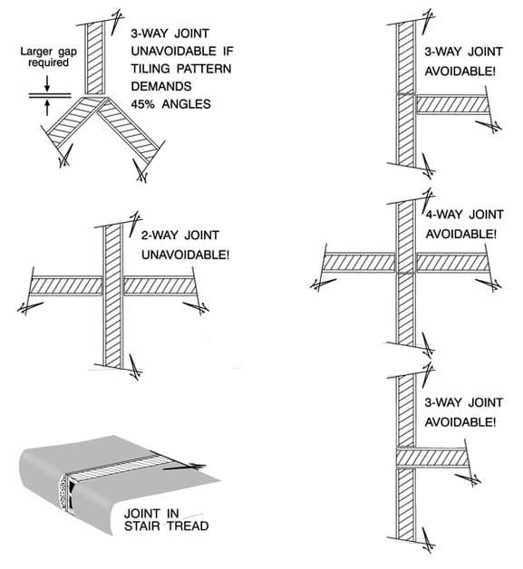
Both preformed metal-neoprene and site-applied elastomeric sealant joints ultimately resist point loads and rolling loads through joint-to-tile adhesion or joint-to-bedding anchorage. Joints installed slightly below or flush with surrounding tilework and stonework are normally protected from direct downward loading and impact other than from stiletto heels, studded sports shoes and skateboards. However joints are sometimes installed slightly above bounding floor and pavement finishes, either through poor workmanship or to cope with irregularities in materials chosen for their rough texture (e.g. exfoliated granite, porphyry and bluestone paving sets, sawn laterite) or produced with slight undulations (e.g. some “rusticated” terracotta and rough-glazed tiles). Designers, specifiers and floor layers should recognise that joints in rough-textured pavements must be fixed and finished at a level somewhere between highpoints - where the joint may be vulnerable to mechanical damage - and low points - where weak tile and stone edges may be exposed and where dirt may collect in deep recesses. Compressible materials and gaps below expansion joints cannot alone support the joints against normal pedestrian traffic. Loads on a Latham Loc Strip Expansion Joint are resisted by a combination of the inherent stiffness of the strip, support from nearby wire anchors and minor support from mortar tamped around the shallow punched anchoring loops. Normal loads applied along a preformed movement joint strip are carried by nearby pairs of wire anchors. However a strip cut short for a butt-joint, with no anchoring loops within as much as 150mm of its ends, may deflect load as a short cantilever and become permanently displaced. It is important to provide anchorage close to butt-joints and to minimise free ends at three-way and four-way intersections. Movement joint strips of less than 400 millimetres, i.e. where three pairs of anchors cannot be installed, should be avoided. These simple installation principles, often overlooked, are illustrated below.
Latham Loc-Strip joints are highly durable and resistant to chemicals commonly found on building sites. However liberal use of dilute hydrochloric acid (also known as muriatic acid) for stripping cement residues from exfoliated granites and other stone finishes is as damaging to brass and zinc Loc Strip edges as to aluminium shop-front sills and steel reinforcing mesh. Alternative cleaning methods should be employed.
Movement Joints for Terrazzo Floors
A range of Latham Loc Strip Joints has been specifically designed for terrazzo insitu and tile flooring where joints must tolerate processes of finishing, grinding and polishing. All Neoprene-X-Pansion joints of 31 mm, 40mm and 50mm overall depth have 6mm and 12mm wide trafficable neoprene wearing surfaces preground and dressed in factory. The product as delivered to site may be incorporated in insitu ground, trowel finish and tile terrazzo floors and is not adversely affected by grinding and polishing up to a depth of 3 millimetres. In selecting preformed movement joints for terrazzo floors, the specifier should ensure that elastomeric core material removed by grinding is not so great as to critically degrade the puncture and load resistance of material remaining between the finished surface and the top air channel.
Illustration Detail

Some Common Errors To Joint Installation

Misalignment of structural movement joints
Misalignment of structural movement joints in concrete slabs and the corresponding movementjoints in tiling has caused extensive cracking in publicareas of a shopping plaza. One solution wouldbe to commence tile set-out from the structural joint line.

Unanchorable short lengths
An unanchorable short length of less than 2 centimetres has been used at this butt-joint; note that the short length is under less compression than the abutting section. At the other extreme, a short gap in the perpendicular joint run, less than 5 centimetres from the intersection, has been filled with dense and incompressible grout.
Combination of mechanical damage
 A combination of mechanical damage, where the Latham joint projects above the level of depressions in exfoliate granite paving, and green staining from strong acids used to remove cement residues. The designer must compromise between placing the joint where it is vulnerable to impact and rolling loads, or fixing it at the lowest level of the pavement surface and subjecting stone edges to damage and soiling. One solution to the problem of straight joints through irregular surfaces is to incorporate bands of relatively smooth stone along movement joints.
Discontinuous joint
 A discontinuous joint set far above the surrounding tiled surface and aligned against an off-cut which is narrower than the movement joint itself. Impact forces against the projecting joint are transmitted into the grout. Strain from thermal expansion and contraction concentrates around the free end of the joint and cannot be accommodated beyond the joint line. The grout will eventually fracture. Unbroken movement joints should always sub-divide pavement and tiling into simple shapes.
Loose three-way butt joint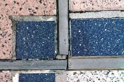
A loose three-way butt joint between the smallest tiles in an elaborate pavement pattern. Tiles, grout and joints in this small area are unable to share in resisting loads. Such co-incidence of butt-joints is easily avoided. Wire ties were omitted from the joints in this example. Had they been installed, the end of each joint would be anchored to a cut tile too small to resist displacement.
Omitted anchors
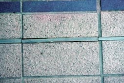 The maximum number of anchors possible along this short length of Latham movement joint is two. The minimum number is one. In this example, anchors were omitted, so the joint was readily distorted and dislodged by mechanical damage. Normal thermal movement of the pavement concentrated across the joint ends and grout detached from its sides. Anchors should be located near the ends of every strip.
Failed four-way butt joint
 A failed four-way butt joint in reconstituted granite at a shopping centre. One of the Latham joints should continue through the junction to distribute loads - and therefore support - between pairs of anchors. The intersecting joint strips should be sized to position anchors close to the otherwise free ends. In this example, the standard wire anchors were omitted.
Complex installations
 Complex joint installations If there must be a choice between cutting tiles to suit non-rectilinear pavement patterns, and geometrically complex joint installations, acute angles in cut tiles set against movement joints should be avoided. The smooth sides of the movement joint do not contribute significantly to supporting the tile against vertical loads, so that tiles cut on acute perform as cantilevers and often fracture.
Drummy tiles along the joint line
 A conventional Latham movement joint removed from a tiled pavement with bands of drummy tiles along the joint line. A bead of stiff dense cement grout has flowed into the trowel-cut groove under the Latham joint. The preformed compressible joint performed as expected, but the underlying grout obstructed movement below the joint’s bottom edge, causing horizontal shear cracks through the mortar bedding. There is no point inserting movement joints, which do not continue in some form through the full depth of the bedding.
Product Specifications How to Specify Guide


.svg "Logo (2)")
